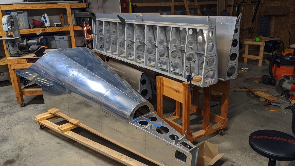
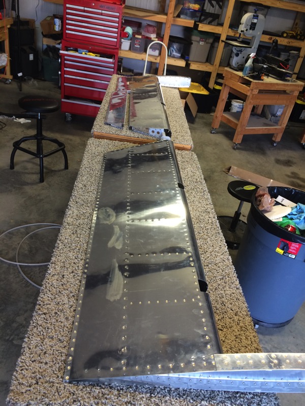
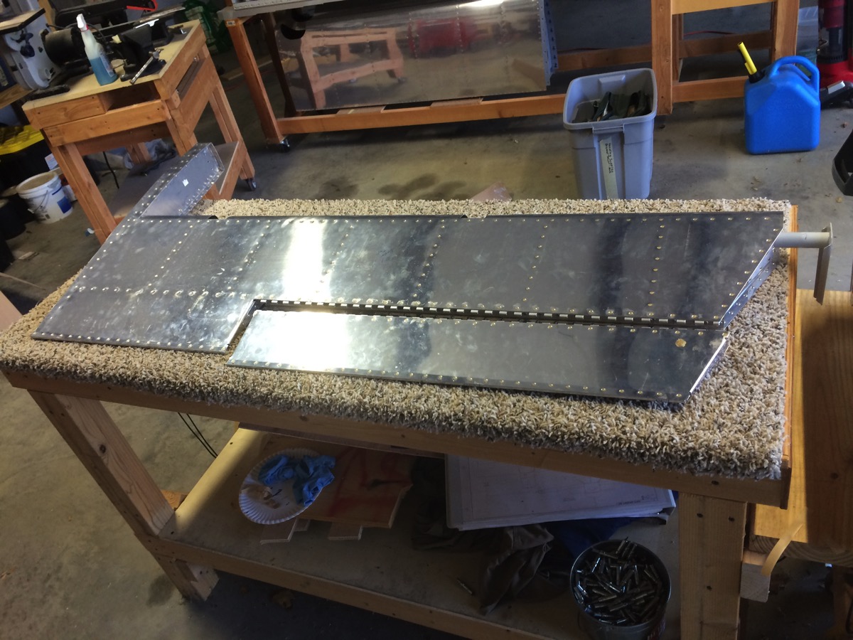
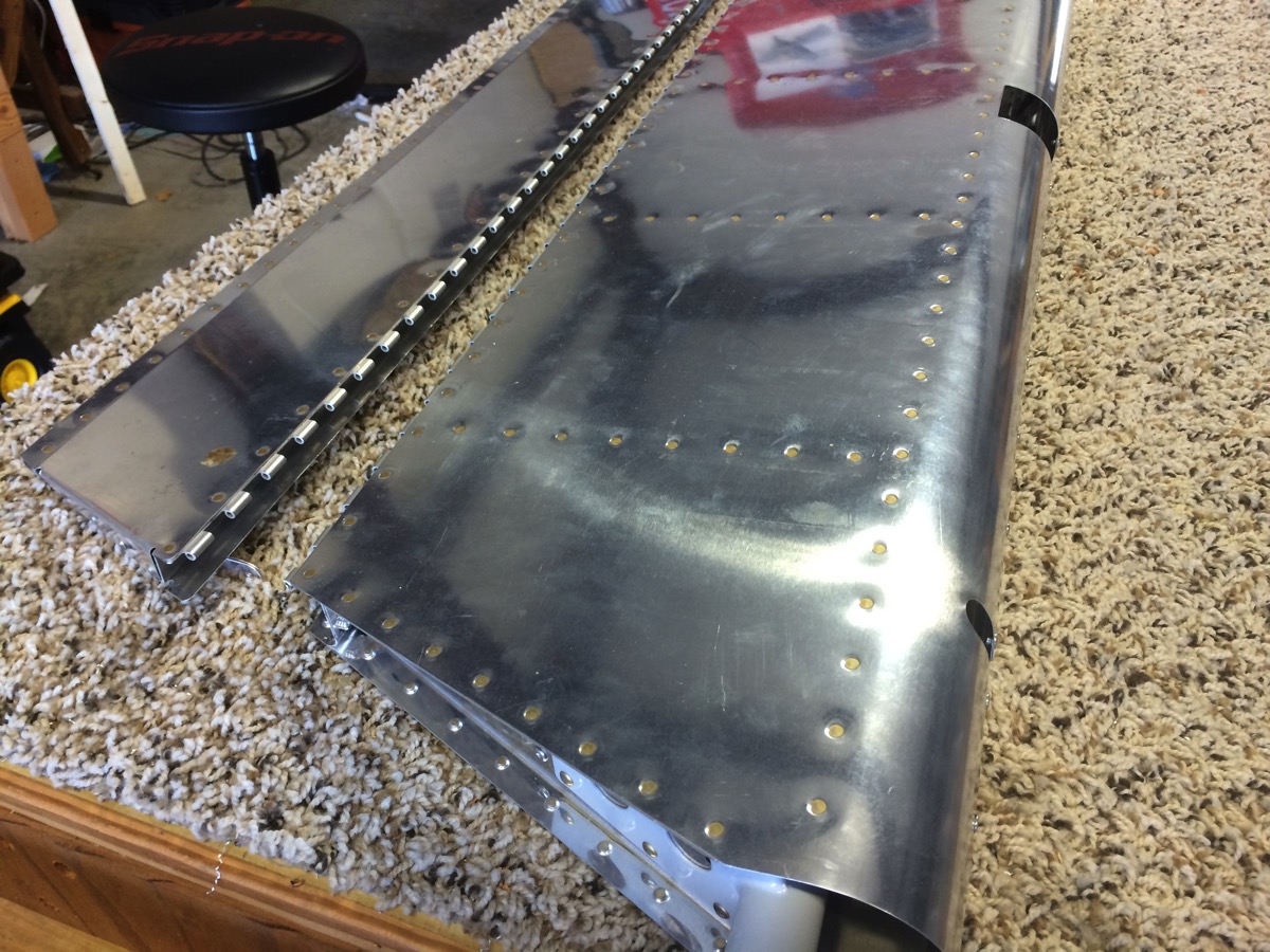
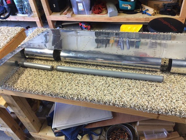
Major Milestone – Finished the Fuel Tanks – Is it Possible?

Got a bit of catching up to do here and I don’t have a lot of pictures so I’ll just get with it.

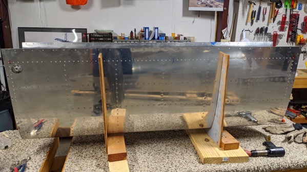
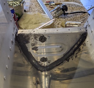
Since last update, I completed closing the right side tank by pro sealing and riveting the aft tank baffle. Right side went much like the left but I think I was a little more tidy with proseal along the skin to baffle rivet line so it didn’t squeeze out through all of the rivet holes nearly as bad.  Also, I only had time to do the Z-Bracket pop rivets so I let the skin-baffle rivets set up overnight under 100% clecos and riveted the next day.  That method is so much cleaner.

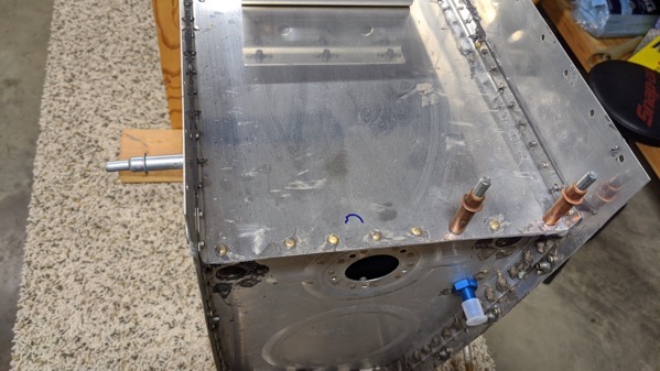
Now the final tasks for closing the tank are to proseal and install the fuel level sender and to install the various fittings for the fuel pick up, tank drain, etc.  I did the senders first.  That involves putting a thin smear of proseal on the tank’s mating surface then maneuvering the float wire and mechanism into the tank.  Then slowly tightening down the 5 cap head screws to evenly squeeze the proseal for what is essentially a “cured in place” gasket.

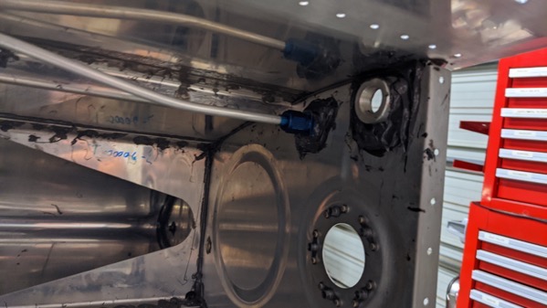
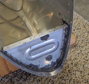
Last item to close the tanks and get them ready for leak testing is to install the fittings.  This can be counted as a lesson learned too late but it turned out ok in the end.  As I was preparing to install the tank drain fitting, I noticed that about 3/4 of the hole was blocked by proseal.  This would have been much easier to clear out from inside the tank before closing but it was too late for that.  So I ground down a razor blade so it was very narrow so it would fit into the drain hole. I then carefully carved away the proseal while being careful to extract the pieces so they wouldn’t become FOD in the tank.  It worked fine just took longer than it should have.

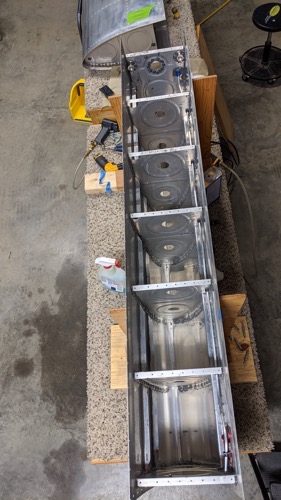
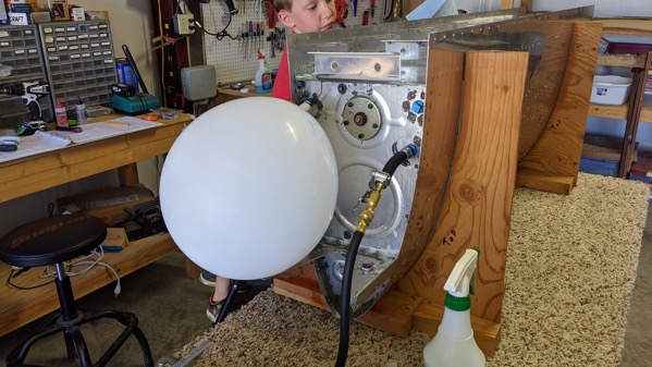
So finally, one of the days I’ve been apprehensive about since starting this build.  Yesterday was time to leak test the completed tanks.  The setup looks something like this, with a balloon on the fuel pickup fitting (secured with a zip tie) and a hose with a Schrader valve to allow for “pressurizing” the tank.  As long as the balloon is inflated, you know that there’s positive pressure in the tank so any leak should result in air coming out, and bubbles in soapy water.
IMG 20200606 140343 copy 

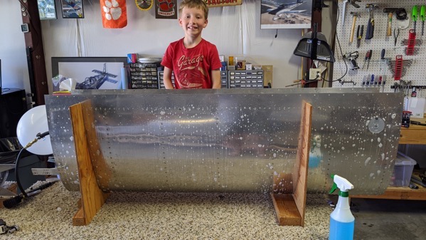
In an ideal world, the test fittings themselves wouldn’t leak so you could observe that the balloon doesn’t deflate.  Bun in my case, there was a leak around the balloon itself so I simply sprayed the entire tank with soapy water to look for bubbles.  I paid special attention to the troublesome areas such as the corners where three pieces of aluminum come together, the fuel sender, and everything having to do with the baffle.
IMG 20200606 135952

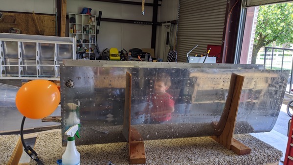
In the end, the only leak I found was around the fuel cap on the right wing.  The fuel caps are adjustable so I can adjust it a little tighter but in reality, that’s at the tippy top of the tank so I really doubt it will be an issue even if I didn’t.
IMG 20200606 142327

I couldn’t be more excited to be past this milestone.  I will probably perform this test once more before hanging the tanks on the wing just to be sure but at least now I know they’re not leaking like a sieve.  

Closed the left tank

Alright, for better or for worse, the left fuel tank is sealed. I’ve gotten back into the habit of going to the workshop after the kids go to bed instead of watching re-runs of Forged in Fire so I’ve gotten some time in over the last couple of weeks.

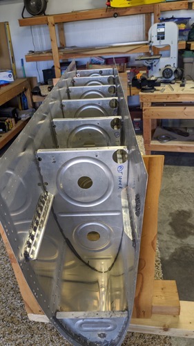
After preliminary leak test, I pro sealed up the tank skins and the ribs and slid the “baffle”, or aft bulkhead, into place and 100% clecoed then riveted

.IMG 20200524 235023

And… in full disclosure, I was an idiot and left off the most inboard Z-Bracket and drove a handful of rivets. I know, I know.

IMG 20200524 235029

So I opted to let the proseal cure before trying to remove those rivets and properly install the bracket the next night.  So after curing for 24 hours, I removed the rivets and fixed the bracket.

So left tank closed.  I’ve ordered some loctite from the aviation section of Amazon that I need to finish installing the fuel fittings.  While I wait for that to arrive, I’ll probably switch over to the right side.


More work on the tanks… both of them

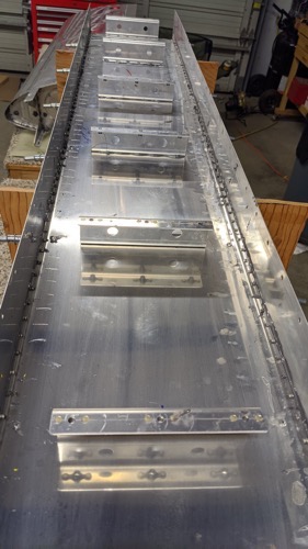
Spent a couple of sessions this week working on the right fuel tank. Attached the outboard tank rib, sealed up all of the rivets for each of the ribs.  Made sure there is a good bead along each edge and ensured that all of the vent openings and the stiffener channel is free of proseal.  That stuff is nasty.

Next up is the top skin J-stiffener.  It’s a bit of a mess to do because you have to apply proseal then try to work it through the small channel opening all the way into the tank. I took the approach of applying a relatively thin coat of proseal to the stiffener before inserting, then after I got it in the channel, I pulled the stiffener away from the skin as best I could and used the sealant gun to squirt more sealant in-between.  Worked good I think.  I 100% clecoed and observed good squeeze out along the stiffener.  I let it set over night and riveted it the next day

Next up was the tank attach bracket and the inboard aft rib.  Both pretty straight forward.  Proseal, 100% cleo and I went ahead and riveted these wet.  Only hiccup was that I put two rivets in a spot on the tank attach bracket that I should have waited because it also had to go through a tab in the inboard aft rib.  So after removing those rivets, I got the inboard aft rib in place and riveted it.

IMG 20200513 183752

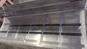
The J-stiffener with proseal on the rivet shop heads.

IMG 20200513 183808

The tank with all but the attach bracket and the inboard aft rib and the aft bulkhead.

IMG 20200516 194552

Tank vent line installed

IMG 20200516 194627

Getting closer

IMG 20200516 172026 MP

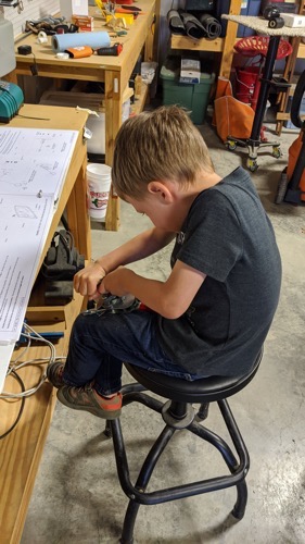
Grayson using a scrap piece of the 1/4 inch aluminum tubing to learn how to form a proper flared end.  These are the (short little) times that I dreamed about when I found out we were having our first baby the same month I started this build.

Inboard Ribs, Proseal and Riveted

Last weekend I set up the inboard fuel tank ribs with proseal and 100% clecos.  I allowed them to set up over night and began riveting on Sunday.  I did roughly 1 rib a day for the rest of the week and today finished the last of the 5 inboard ribs.

IMG 20200508 165042 MP

So not done with proseal by any means but making progress towards that end.

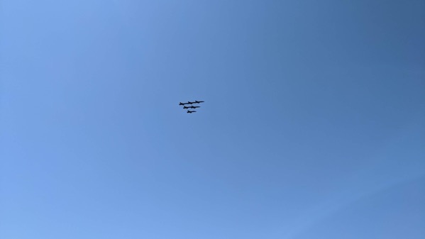
On Wednesday of this week, we took a little bit of time and went so see the Blue Angels fly over to recognize the healthcare workers during the Covid-19 crisis.

IMG 20200506 112115

Right Wing, First Rib

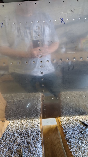
The proseal set up overnight and looks pretty good.  So I took an hour today while the boys were playing on the slip and slide to rivet the first rib.  I do like this process better than the wet proseal method.  Here’s the top of the wing skins with the first inboard rib riveted: 

IMG 20200503 180059

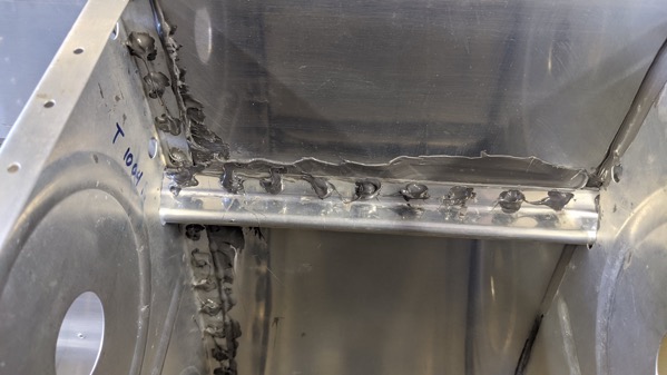
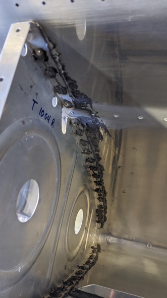
Here’s a view from the inside of the wing showIng the proseal added on top of the completed shop heads.

IMG 20200503 180127

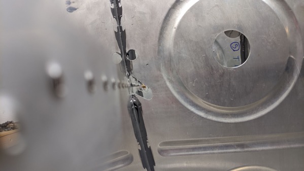
That big glob of smeared proseal is a result of trying to clear out the channel for the J-stiffener which will be installed after the inboard ribs are completed.

Here’s a view looking down the J-stiffener channel…

IMG 20200502 205842

Proseal on the Right Tank Ribs

I been watching Jason Ellis’ fantastic YouTube channel as he’s building his RV-10.  He did his tanks with a different technique than I used when I did the Left side tank.  So I thought I would try something new.  

If you recall from my highly rated and critically acclaimed post “Fuel Tanks 4”, I used the technique of applying proseal then allowing it to set up with clecos before riveting (with more proseal) the next day.  

Essentially, the difference is that Jason applied proseal then riveted while the proseal was still wet.  Then allowed the proseal to set up overnight before proceeding further.

So I tried it on the inboard forward half rib.

IMG 20200502 185027

It’s messy stuff.  And here’s a view from the inside

IMG 20200502 185032

There are gaps in the aluminum where it’s formed to create the rib flange down by the nose so you have to be sure to get those filled with proseal.

But in the end, I decided to go back to my previous technique for the remaining ribs.  I just think it is a little less messy.  So I applied proseal to the 5 inboard ribs and will allow them to set up overnight under 100% clecos before moving to the rivet steps.

IMG 20200502 211525

IMG 20200502 205624

I then used the remaining proseal to apply a fillet to the non-flange side of the ribs.  I’ll worry about the flange side after riveting.

IMG 20200502 205641

Fillet on the left and you can see pretty good consistent squeeze out on the flange side of the rib on the right.

Sealing the Right Tank Baffels

Started working on the right side fuel tank again.  I had previously cleaned up the pro seal left from riveting the tank stiffeners that I did several years ago.  Today I applied proseal to the rivets and mating lines.  I mainly did this just to have a low impact task to get back in the swing of using proseal again.  It really is some nasty stuff.

IMG 20200501 131655

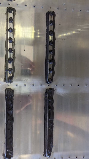
I initially just penutbutter spread the proseal across the rivet line but that was using a lot of proseal.  So I switched to doing generous blobs on top of each individual rivet.  I think either will seal just fine.

IMG 20200501 131703

Back at it!

Well the COVID-19 shutdown has had the effect of giving me more time around the house. So I have taken the opportunity to dust off the empennage and do the last few items that I need to do prior to switching back to the tanks and wings.

IMG 20200420 192309

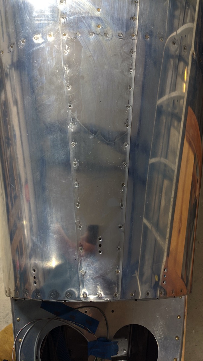
I did the aft 27 rivets on the top skin of the tailcone. That finishes up the emp skin rivets except for a couple dozen that I need a helper to get. So those will wait.

IMG 20200420 192328

I built a little cart to hold the tail cone so I can get it off the workbench. Next step will be to buy some new Proseal, clean up the right side tank skin, and get ready to do dirty work again.

DRDT Laser Sight

I had a small Christmas break project that may be worth reporting.

It has always driven me a bit crazy using the DRDT-2 on large pieces. I had a tendency to fish around trying to get the die to mate with the rivet hole, putting small scratches on the piece. So I decided to make a laser sight.

I think there are various ways to accomplish this task, this is what I chose:

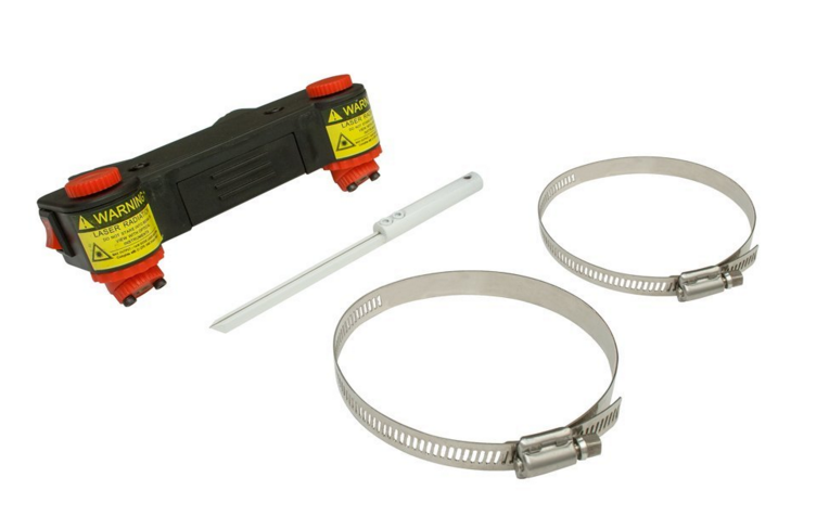
Step 1: Acquire Laser. In this case, a Drill Press laser sight from Amazon for $40.

Screen Shot 2016 01 01 at 3 40 12 PM

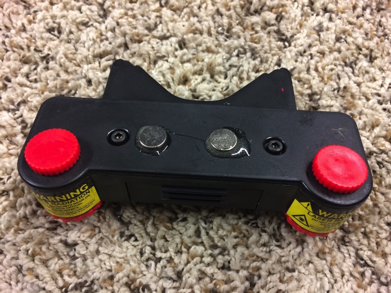
Step 2: Epoxy rare earth magnets to the case of the laser. I used rare earth because they’re thinner. This thing already sticks down into the neck space of the DRDT enough.

IMG 0398

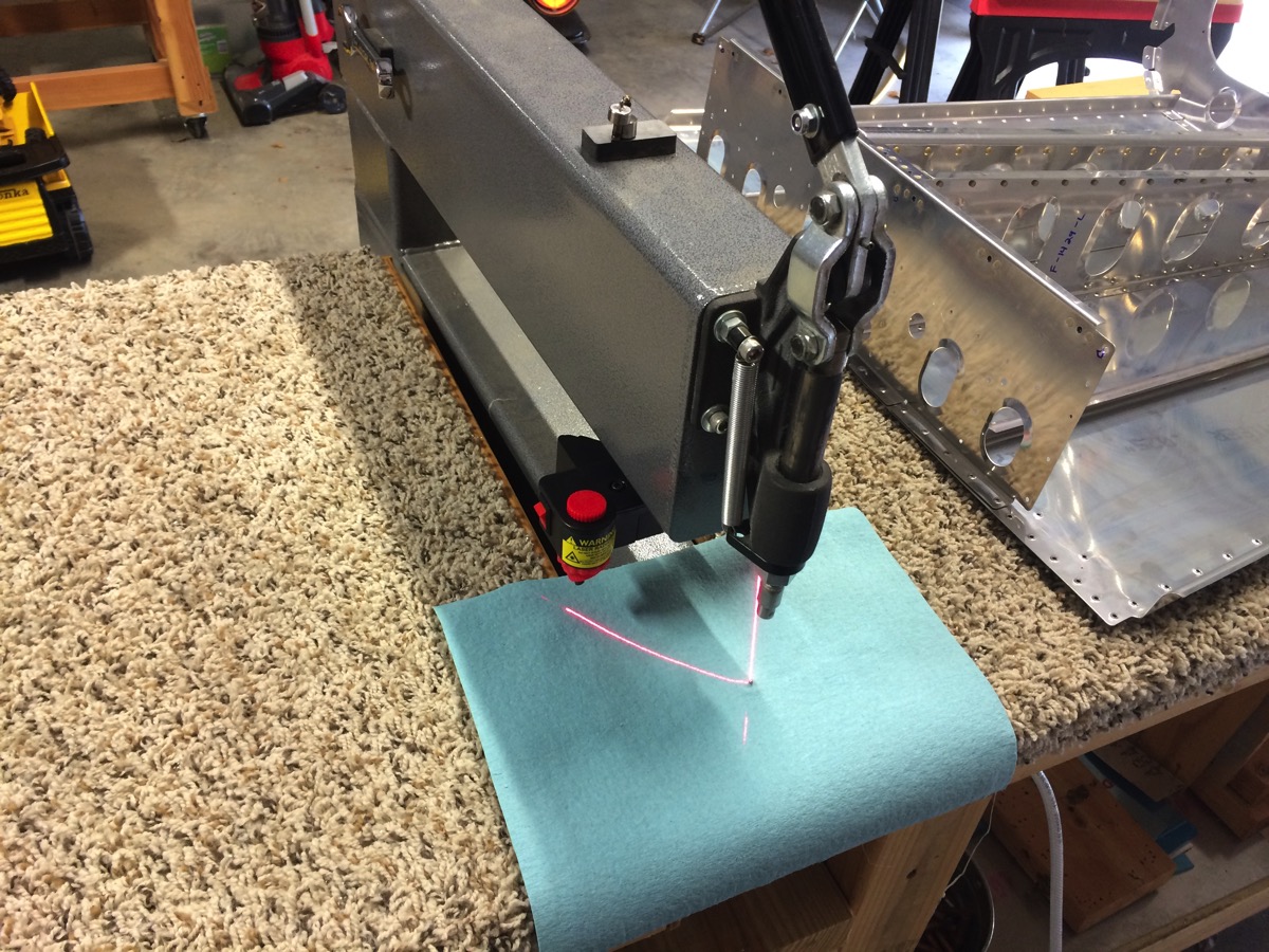
Step 3: Attach the laser to the DRDT and adjust. The laser is fully adjustable but I think the easiest thing to do is get it roughly adjusted then just move it around slightly until the X hits the dimple die.

IMG 0399

As I said above, it does stick down into the open neck of the DRDT a little, maybe an inch or so. It may not be usable for anything other than large flat pieces but if I want to remove it, I’ll just take it off and the magnets will stick it to the top of the DRDT where I store some Dies, etc.

After I ordered the laser sight, I saw something online that gave me another idea for a solution that may be better. You could just use a regular office laser pointer with a magnetic helping hand (the kind they use in electronics and stuff to help solder). The only trick there would be devising something to keep the button pushed but I’m sure something could be worked out. That would have the advantage of not sticking down into the free space. And since the die doesn’t move up or down, a single laser dot would do the job just fine.

I’ve got some big skins to dimple this weekend so I’ll report back how it does.

Elevator

I’ve finished all of the elevator except for wiring the trim tab servo. I had to order a crimper and some Molex pins that were missing from my kit.

IMG 0057

The main thing that I had to rework was the trim tab hinge. I attached both of the halves of the piano hinge as per the instructions but the half on the elevator spar was warped.
IMG 0058
I ordered replacement parts, drilled out the bad piece (about 25 rivets) and redid that hinge. This time, I kept the hinge assembled while I positioned and drilled the hinge. This kept the piece from warping.
IMG 0063

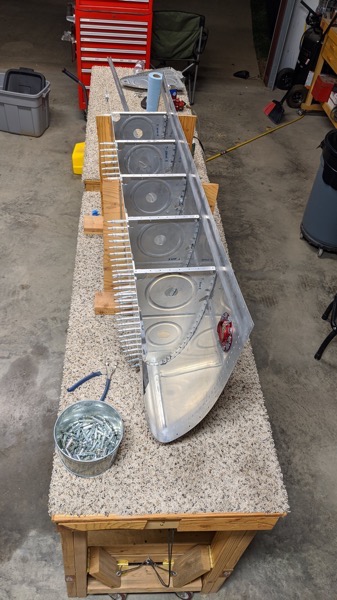
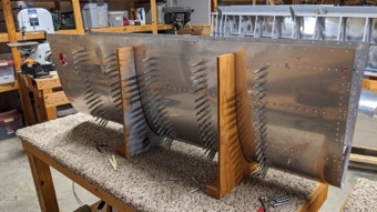
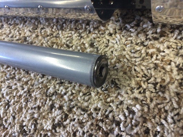
Anther thing worth noting is that I built a tool to make rolling of the leading edge easier. This idea was something I got from a post on =VAF= and is simply a closet rod with a 7/8 inch socket epoxied into the end. This lets you use a socket wrench to do the turning instead of vise grips on a broomstick. I made two: one long one with a socket on both ends, and one short one with one socket for use on the short section at the end. By my counting, this is the last rolled edge on the plane so I probably won’t use it again but it was well worth the effort to build.

IMG 0055IMG 0056