I’m Still Working on it

I know it’s been 12 months to the week since I published anything here but I am still working on the build. I’ve had to prioritize things a bit. Given much less time available to build, I’ve been spending what time I do have in the workshop instead of on the computer writing about it. I would like to pick the blogging back up so I intend to get something of a catchup post out at some point during the holidays.

In general, I’ve continued to work on the empennage kit, completed the V Stab, H Stab, Rudder and am just wrapping up work on the elevator and trim tab assembly. I will be starting the tail cone (Chapter 10) this week.

After that, I will return to the wings and finish the fuel tanks and the rest of the wing construction before biting the bullet to buy the Fuselage kit.

Rudder

Section 7 is the rudder. I started working on the rudder over this long Thanksgiving weekend and have gotten a good number of hours in. There’s a surprisingly large number of parts in the rudder assembly and the first several steps involve separating parts and deburring.

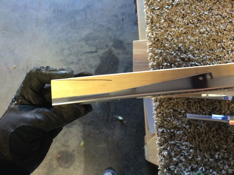
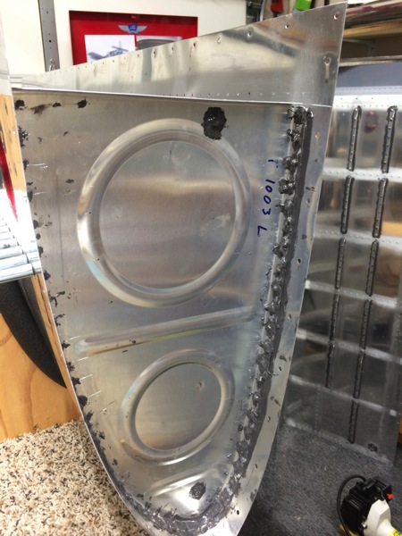
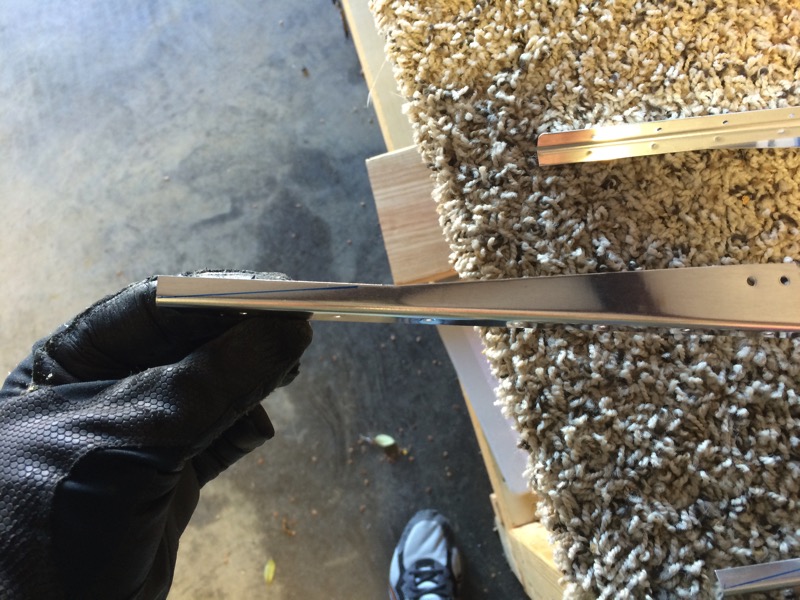
I do have one small tip when it comes to cutting the stiffeners. The plans have you draw a cut line on each stiffener then trim along the line. Below you can see the cut line on one of the stiffeners.
IMG 3862

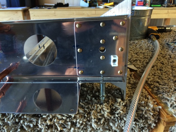
I nested a 1×2 piece of scrap wood in the bend of the stiffener and carefully cut the first stiffener with the band saw. This resulted in a cut in the 1×2 that served to guide the band saw blade for each subsequent stiffener I cut. I just had to align the end of the stiffener with the end of the 1×2. Since there are Right and Left hand stiffeners, I had a cut on each side of the 1×2 that you can see below. This made quick work of what is normally a tedious job.
IMG 3864

After getting all of the parts cut and deburred, It’s time rivet the hinge doublers to the spar
IMG 3875

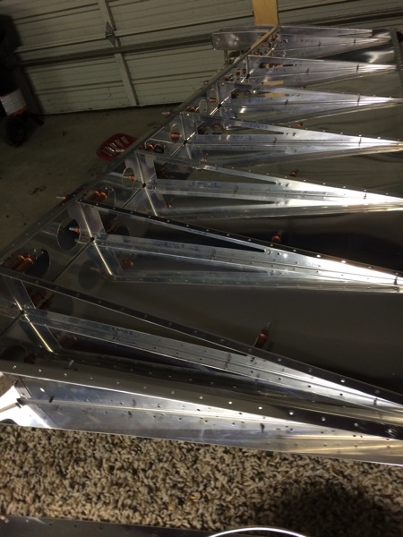
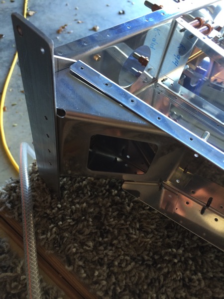
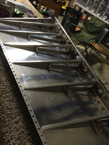
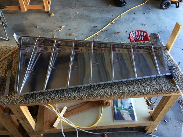
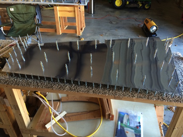
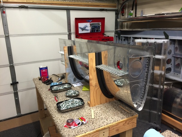
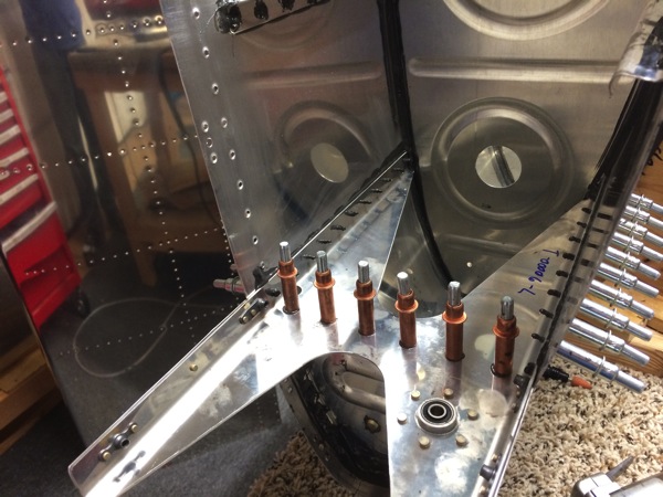
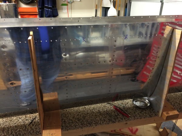
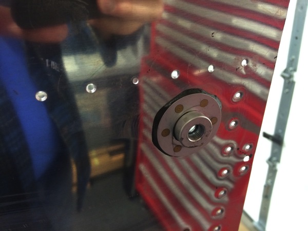
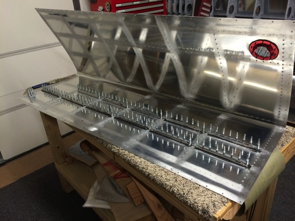
and assemble the rudder skeleton and skin for some match drilling.
IMG 3877

IMG 3876

IMG 3878

IMG 3874

IMG 3873

After some match drilling, including the trailing edge, It is time to disassemble and debur everything. More on that tomorrow.

Vertical Stabilizer

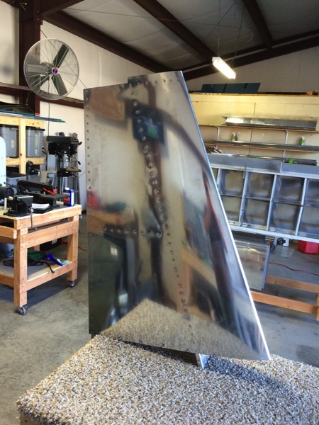
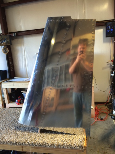
Completed the Vertical Stabilizer last weekend. It’s exciting to be working aluminum again. I opted to skip (backwards) in the plans rather than dive back into proseal and fuel tanks right off the bat. Since I have the Empenage kit I opted to get started on the vertical stabilizer. Unfortunately, I neglected to take many pictures. I guess that’s a habit to get back into also.

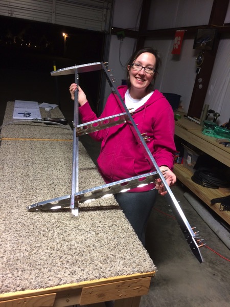
Here is Ashley holding up the clecoed stabilizer skeleton after the first day of building in over 6 months.
IMG 3833

and fast forward to the end product, the completed vertical stabilizer
IMG 3855IMG 3854

Another note to get out of the way, I have opted not to prime the pieces going forward. This is an item that receives quite a bit of debate but the bottom line is that I live in mostly arid climate and there is little real evidence that I’ve seen that shows corrosion on 2024-T3 aluminum. There are thousands of Cessna aircraft out there built in the 50’s and 60’s with 2024 that were not primed and are flying today. I started the build not knowing for sure which way I would go so I opted for the “may as well prime because I can decide not to later” approach. As I went through the build, I found how much additional time priming took so now is the time that I decide not to.

Move complete and new workshop ready

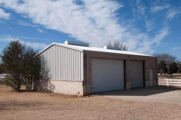
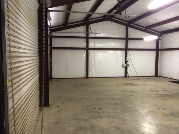
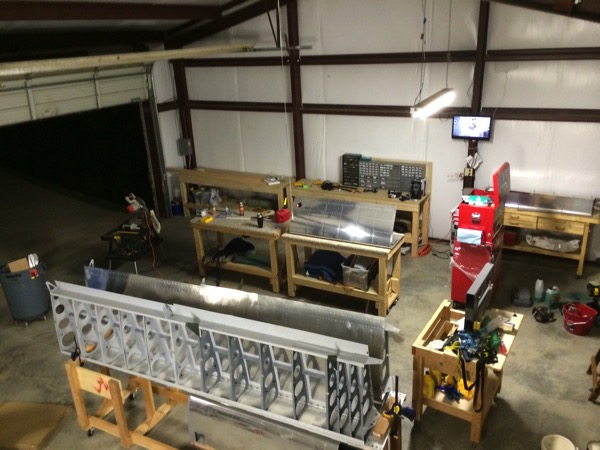
Well, It’s been quite a while since I’ve made an forward progress on airplane building. Here is a big part of the reason. Ashley and I decided to sell our house and move to the Burleson area. We wanted a place large enough for a little boy to run around and get into trouble without having to cross city streets. I, of course, also wanted larger workshop space.

So……
IMG 3282

30×40 workshop / Airplane factory
IMG 3381

and, after a ton of help from Dad and a successful move…
IMG 3660

Since I can’t hang stuff on the walls here very easily, I had some fixtures to build. So that took a good bit of time but now I’ve got a great deal of storage and workbench space and I’m ready to start working aluminum again.

Fuel Tanks 5

Been quite a while since I did any productive work on the wing kit after working on Emp inventory, dealing with a flu bug, etc, etc. I know, excuses, excuses…

Did a little more work on the left fuel tank. Last weekend I sealed and riveted the outboard end rib, and the inboard fwd half rib.

Mom and Dad are in town for a day so today we prosealed the J-stiffener and the tank attach bracket. We’ll drive the rivets tomorrow.

Tank with the J-stiffener and bracket clecoed in place to set up overnight.
IMG 3170

the outboard end rib riveted and sealed
IMG 3171

Fuel tank attach bracket
IMG 3172

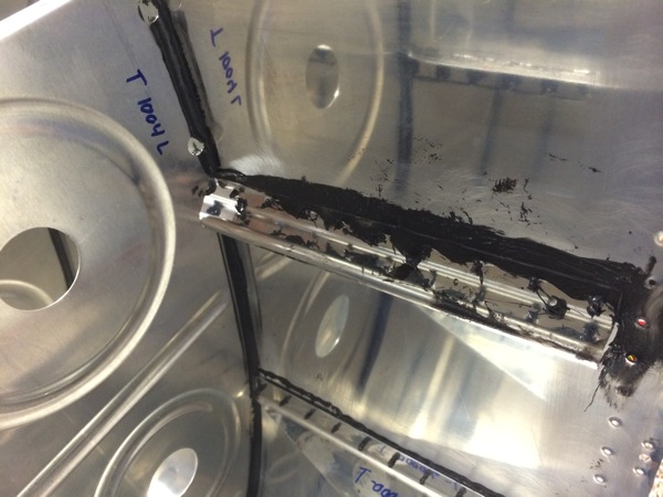
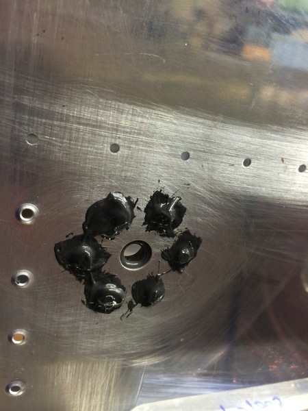
Sometimes the proseal plays nicely and you get a nice looking sealed surface with nice squeeze out…
IMG 3174

…and some times the proseal gets angry at you…
IMG 3173

Empennage Inventory Complete

Ashley and I finished inventoring the Emp kit today. The only thing missing was 6 molex pins and a few AN470AD3-3.5 rivets. Normally I wouldn’t worry about the rivets but I don’t have any of these so I’ll ask Van’s to send them.

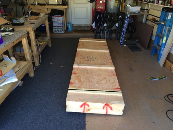
Here’s a picture of the unopened box. I’ll get some pictures of the stuff all stored away in the garage soon.

IMG 3122

Fuel Tanks 4

Last day that dad’s in town so I’d better get a full day’s work out of him…

We started by riveting the stiffeners, drain flange, and fuel filler flange on the right wing. Then we put the left side back in the cradle and set up to rivet the ribs. This is the time that fuel tank construction gets serious. For each rivet, the process goes something like:
1. Remove Cleco
2. Clean out hole of excess sealant from the overnight set up
3. Apply small dab of sealant to the dimple
4. Insert rivet. It will sit in this bed of fresh sealant.
5. One person holds the bucking bar, the other drives the rivet.
6. Repeat about 30 times for each of the 5 inboard ribs.
7. Use a small brush and apply a dab of sealant to the newly formed shop head of each rivet.

Short version of the story is that we worked all day and finished the inboard ribs.

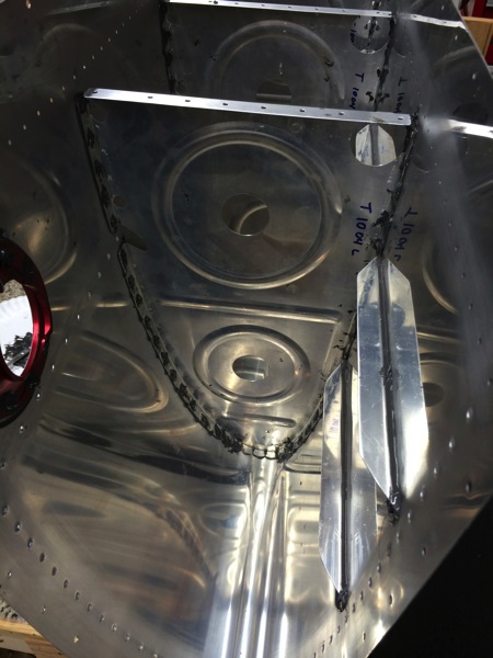
One of the inboard ribs
IMG 3100

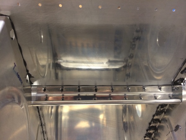
Bottom of the fuel tank. You can see the vertical rows of rivets for the ribs and the horizontal rows for the stiffeners
IMG 3101

Fuel tank drain flange
IMG 3102

Inside of the fuel tank drain. You get a good look at the sealant applied to the rivet shop head.
IMG 3103

I’m very pleased with the progress we made over the past week. We worked nearly 30 hours (58 man hours) and made significant progress on the fuel tanks. Thanks for the help Dad!

Empennage!!!

I placed the order for the Empennage and paid the balance today. Van’s expects it to ship next week so I’ll probably be seeing it around mid January. Of course, their website says that they have a 10 week lead time…guess not! Suppose that means I need to get busy and make some room in the workshop…

Fuel Tanks 3

We decided to let the left tank ribs set up another day so we worked on the right side today. We got the skin dimpled, J-Stiffener fabricated, tank-baffle holes countersunk, and sealed the fixtures onto the inboard rib (sealed and clecoed, rivet tomorrow). We also got the tank skin stiffeners pro sealed and clecoed onto the skin awaiting rivets tomorrow.

Here’s a few pictures:
IMG 3094

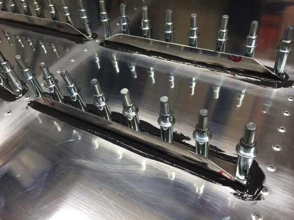
Here’s a little closer look at the stiffener with pro seal squeeze out.
IMG 3096

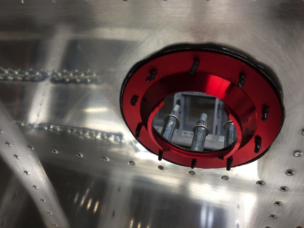
And here’s a look at the fuel cap flange clecoed to the top surface of the skin.
IMG 3097